The sensor that rotates a smartphone screen and the sensor that keeps an uncrewed aircraft on course are, at heart, the same kind of device: an inertial measurement unit (IMU). Yet their performance requirements differ. One needs to be good enough to tell which way up a phone is held, while the other has to track position for minutes at a time without any outside reference.
This article explains what an IMU measures and how micro-electromechanical systems (MEMS) sensors detect motion. It then covers how that data becomes a navigation solution, and why the electronics around the sensing element play such a large part in deciding how accurate the result is.
What an inertial measurement unit measures
An IMU measures motion without reference to anything outside the body it is attached to. It typically combines three types of sensor:
- Accelerometers measure specific force: the acceleration experienced by the sensor relative to freefall. An accelerometer resting on a desk reads 1 g, while one in freefall reads zero. By measuring the direction of gravity across its axes, an accelerometer can also sense tilt when the device is stationary or moving slowly.
- Gyroscopes measure angular rate, which is how quickly the body is rotating about each axis.
- Magnetometers, where fitted, measure the local magnetic field to provide a heading reference relative to magnetic north.
Each sensor measures along or about a single axis, so sensors are mounted in orthogonal sets of three, known as triads. Three accelerometers and three gyroscopes give six degrees of freedom (DoF), and adding a three-axis magnetometer creates a nine-DoF unit. Rotation about the three axes is usually described as roll, pitch and yaw.
This is why an IMU is more than an accelerometer. Acceleration alone cannot reliably separate a change in tilt from a change in speed. The gyroscopes provide the rotational information that makes that distinction possible.
How MEMS accelerometers, gyroscopes and magnetometers sense motion
Most IMUs outside the very highest performance grades use MEMS sensors. These are mechanical structures, measured in micrometres, that are etched from silicon using processes similar to those used to make integrated circuits.
Accelerometers
A MEMS accelerometer contains a small proof mass suspended on silicon springs. When the sensor accelerates, the proof mass lags behind and the springs deflect by an amount proportional to the acceleration. The proof mass forms one side of a set of capacitors, often arranged as interleaved combs, so its movement changes the capacitance between it and fixed electrodes. Measuring that change differentially, with one capacitance rising as the other falls, helps cancel errors common to both.
Gyroscopes
A MEMS gyroscope has no spinning rotor. Instead, a proof mass is driven to oscillate continuously at its resonant frequency. When the sensor rotates, the Coriolis effect produces a force at right angles to that drive motion, proportional to both the rotation rate and the velocity of the mass. This causes a small secondary movement, which is detected capacitively. Because the drive motion is oscillating, the rotation signal appears as a modulation at the drive frequency and has to be demodulated to recover the angular rate.
Magnetometers
MEMS-scale magnetometers commonly use the Hall effect or magnetoresistive materials to measure the strength and direction of the surrounding magnetic field. They provide a useful long-term heading reference, but they are easily disturbed by nearby ferrous structures, motors and current-carrying cables, so they usually need calibrating once installed.
For the most demanding navigation applications, fibre-optic and ring laser gyroscopes offer greater stability, but with trade-offs in size, weight and cost. Where size, weight and power are tightly constrained, MEMS sensors dominate.
In every case, the sensing element’s output is a very small change in capacitance, voltage or resistance. Turning that change into a trustworthy measurement is the job of the electronics, and that is where much of an IMU’s real-world accuracy is won or lost.

From motion data to a navigation solution
An IMU reports angular rates and specific forces. On its own, it does not say where a vehicle is. Most modern systems use a strapdown arrangement, where the sensors are fixed to the body of the vehicle and position is calculated mathematically:
- The gyroscope rates are integrated to track attitude, which is the vehicle’s orientation.
- That attitude is used to rotate the accelerometer measurements from the vehicle’s own axes into a fixed navigation frame aligned with the Earth, such as north, east and down (NED).
- The effect of gravity is removed.
- The remaining acceleration is integrated once to give velocity, and again to give position relative to a known starting point.
Calculating position in this way, from a known start and measured motion, is known as dead reckoning.
Why small errors compound
Because position is calculated by integration, every error accumulates. A constant accelerometer bias produces a velocity error that grows steadily over time, and a position error that grows with the square of time.
Gyroscope bias has an even greater effect. A small gyroscope error tilts the calculated attitude, so a fraction of gravity is mistaken for real acceleration. That leaked acceleration is then integrated twice as well. As a result, position error from a constant gyroscope bias grows roughly with the cube of time. This is why tiny residual biases matter so much, and why gyroscope bias stability is the specification that most often separates one performance grade from another.
IMU, AHRS and INS
These three terms are often used interchangeably, but they describe different levels of capability:
- IMU: The sensor unit itself, reporting raw or compensated angular rates and specific forces.
- Attitude and heading reference system (AHRS): Adds processing, usually alongside a magnetometer, to output orientation and heading. An AHRS does not calculate position.
- Inertial navigation system (INS): Calculates position, velocity and attitude. In practice, most INS units are aided by other sources such as global navigation satellite system (GNSS) receivers, combined through a sensor fusion algorithm.
Inertial navigation and satellite positioning
Satellite positioning, whether the Global Positioning System (GPS) or another GNSS constellation, and inertial navigation have opposite strengths. An IMU provides smooth, high-rate data that is very accurate over short periods but drifts over time. GNSS provides position with bounded long-term error, but at a lower update rate, and its signals can be blocked by tunnels, buildings or terrain.
Whether an INS is more accurate than GNSS therefore depends on the timescale. Fused together, GNSS corrects inertial drift, while the IMU carries the solution smoothly between updates and through gaps in coverage. This is why commercial aircraft still carry inertial reference systems alongside satellite navigation.
Where IMUs are used for navigation
IMUs support navigation and control across a wide range of platforms, including:
- Uncrewed aerial systems. Flight stabilisation, autonomous flight and continuity between position fixes.
- Robotics and automated guided vehicles (AGVs). Navigation indoors and in other areas that satellite signals cannot reach, often combined with wheel odometry and vision systems.
- Agricultural and construction machinery. Precise guidance and machine control, including correcting antenna position as vehicles tilt on uneven ground.
- Automotive. Dead reckoning through tunnels and dense urban areas, along with vehicle dynamics and driver assistance functions.
- Marine and subsea. Navigation for vessels and underwater vehicles, where satellite signals cannot penetrate water.
- Aerospace and space. Aircraft attitude & navigation, and attitude control for satellites.
The requirements differ, but the common thread is that the data has to stay trustworthy across changing temperatures, constant vibration and years of service.

Why the electronics around the MEMS sensing element decide IMU accuracy
What separates a low-cost consumer IMU from one capable of supporting navigation? Part of the answer lies in the sensing element itself, including its mechanical design and packaging. But a large share of an IMU’s error budget is set by the electronics that drive and read the sensing element, and by how precisely they are calibrated. The same MEMS element can perform very differently depending on the signal chain built around it.
As Ross Turnbull, Director of Business Development at Swindon Silicon Systems, explains:
“Modern microelectromechanical systems (MEMS) gyroscopes and accelerometers are compact, lightweight and power efficient, making them well suited to applications where size, weight and power consumption remain tightly constrained. However, their performance is heavily influenced by the quality of the surrounding electronics and signal chain, including analogue acquisition and signal conditioning.”
Reading very small signals cleanly
The capacitance changes produced by proof mass movement are extremely small, far smaller than the stray capacitance of a typical circuit board connection. The analogue front end converts these changes into a usable signal, and its noise floor sets the smallest motion the IMU can detect.
Low-frequency noise and amplifier offset are especially damaging in navigation. They appear as slow drift, which is exactly the type of error that integration turns into large position errors. Techniques such as chopper stabilisation help suppress them. The front end also needs enough linearity and headroom to avoid clipping during shock and vibration.
Because these signals are so sensitive, the physical distance between the sensing element and the readout circuit matters. Placing the interface electronics close to the sensing element, ideally within the same package, reduces parasitic capacitance and susceptibility to electromagnetic interference (EMI).
Controlling the gyroscope’s resonator
A MEMS gyroscope is a resonant system that the electronics must keep running. A drive loop sustains the proof mass oscillation at its resonant frequency and holds its amplitude constant, tracking the resonance as it shifts with temperature. Because the Coriolis force is proportional to the velocity of the driven mass, any variation in drive amplitude changes the gyroscope’s sensitivity directly. This is a scale factor error created by the electronics rather than the mechanics.
On the sensing side, the rotation signal is recovered through synchronous demodulation against the drive reference. Small mechanical imperfections also create an unwanted quadrature signal, 90° out of phase with the rotation signal and often far larger than it. If the demodulation phase is even slightly off, part of that quadrature signal leaks into the output as bias, and that bias can then shift with temperature. Precise phase control and quadrature cancellation are among the most important functions of a gyroscope interface.
Temperature, vibration and electrical noise
- Temperature. The bias and sensitivity of both accelerometers and gyroscopes shift with temperature, as do the characteristics of the electronics. An on-die temperature sensor, combined with compensation coefficients derived from characterisation across the operating range, allows these shifts to be corrected in real time.
- Vibration. When vibration meets any non-linearity in the sensing element or electronics, part of that vibration can be converted into a steady offset. This is known as vibration rectification error, and it is indistinguishable from genuine acceleration or rotation. On platforms with constant vibration from engines, motors or rotors, it creates a bias that only appears in operation. Linear front ends with sufficient headroom, and filtering designed around the platform’s vibration profile, help keep it under control.
- Electrical noise. Autonomous platforms often place IMUs near switching power supplies, motor drives and radio transmitters. Good supply rejection, stable references and careful partitioning between analogue and digital circuitry help stop that noise from reaching the measurement.
Calibration and integration in a mixed-signal ASIC
No two MEMS sensing elements are identical. Offset, sensitivity, cross-axis sensitivity and alignment all vary from unit to unit. These errors are typically measured for each unit during production test, and the resulting correction coefficients are stored in non-volatile memory (NVM), where a digital core applies them in real time. Calibrating every unit against the same references is what allows IMUs to produce consistent data across an entire fleet of platforms.
A mixed-signal application-specific integrated circuit (ASIC) can bring all of these functions together on a single die:
- Low-noise front ends and the gyroscope drive loop.
- Demodulation and analogue-to-digital converters (ADCs) that sample all channels in step, so gyroscope and accelerometer data stay aligned in time during fast manoeuvres.
- Temperature sensing, digital compensation and NVM for calibration coefficients.
Each block can be designed around the characteristics of the specific sensing element, rather than adapted from generic interface electronics. This can reduce noise and board-level complexity, along with the size, weight and power consumption of the overall IMU. For more on how sensor interface ASICs are structured, read our blog on sensor interfacing.
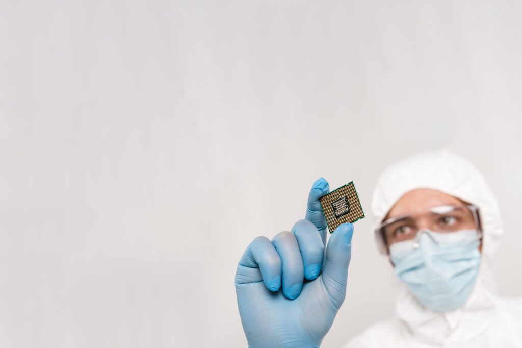
Test capability matters too. Swindon Silicon Systems combines ASIC design and verification with wafer probe and packaged test, and supplies precision calibrated system-in-packages.
Designing IMU electronics for long service lives
Navigation platforms in aerospace, defence and industrial sectors are often expected to remain in service for well over a decade, so continuity of supply for the interface electronics is an important engineering consideration. No supplier can rule out the discontinuation of an underlying process or component. However, an ASIC partner with long-term lifecycle planning can reduce the impact through proactive notice, last-time buys and process migration support.
Swindon Silicon Systems develops mixed-signal ASICs for automotive, industrial, and aerospace & defence applications, including ICs for navigation and ranging. As a full turnkey partner, we cover design, test and supply under one roof. For industrial and navigation products, an ASIC can be viable from 1 – 10K units per year and upward.
To explore whether an ASIC could improve the accuracy and longevity of an IMU or navigation platform, get in touch with the Swindon Silicon Systems team.