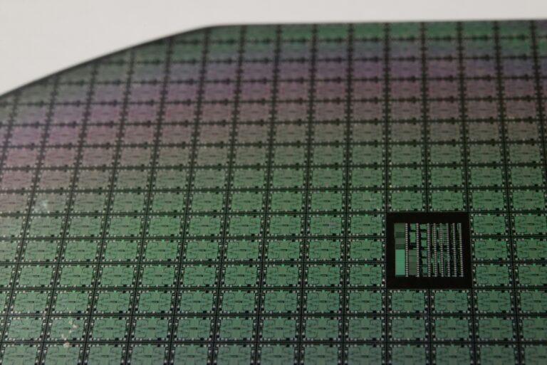
Temperature affects most sensors. A pressure sensor may read accurately at 25°C, but drift when ambient temperature swings to -40°C or +80°C. A position encoder’s output shifts with thermal cycles. The result can be offset error, gain drift, and nonlinearity that pushes readings outside tolerance.
If you are designing a sensor system for automotive, industrial, or aerospace applications, it’s important to design temperature compensation into your ASIC. This will ensure accuracy targets, power budget, and lifecycle requirements are met.
This article explores the temperature compensation methods available, how to integrate them into mixed-signal ASIC design, and how the choice of strategy affects long-term supply reliability across different applications.
Compensation methods: choosing the right approach
Three broad strategies exist, each suited to different accuracy and power requirements:
- Analogue compensation
- Digital compensation
- Hybrid compensation
Analogue compensation
Analogue compensation uses hardware to adjust the sensor signal in real time. A temperature sensor on the die (typically a resistor or diode) measures local temperature, driving one or more digital-to-analogue converters (DACs) that adjust the sensor’s excitation voltage, amplifier gain, and output offset. The advantage is low latency and minimal power draw. The limitation is that analogue compensation corrects only first-order (linear) temperature errors, leaving higher-order nonlinearity unaddressed.
Digital compensation
Digital compensation converts the raw sensor output to digital using an ADC, then applies a correction function (typically a lookup table in EEPROM or a polynomial algorithm). Its main advantage is flexibility: the correction curve can match any error signature your sensor exhibits. The drawbacks are higher power consumption and increased design complexity and cost.
Hybrid compensation
Hybrid compensation combines both approaches. Analogue compensation corrects first-order drift using DACs. Digital compensation then fine-tunes residual error using a lookup table. This method captures the benefits of both and provides low-latency primary correction without the full silicon footprint of pure digital compensation.
Which method is right for your use case?

In practice, the best choice depends on your application. Tyre pressure monitoring systems must tolerate temperature swings from -40°C in winter to +125°C in summer. Hybrid compensation, with analogue gain and offset correction combined with digital linearisation, is standard because sensor nonlinearity is too complex for analogue methods alone.
Industrial vibration sensors used for predictive maintenance may favour analogue or hybrid approaches to keep power consumption low and measurement latency minimal, since these systems often run on energy-harvesting or battery power for extended periods.
Temperature sensors: selecting your reference
The temperature sensor you integrate (on-die or external) directly affects compensation accuracy and power efficiency.
On-die CMOS temperature sensors
On-die CMOS temperature sensors are the standard in modern ASICs. A pair of transistors at different current densities produces a voltage proportional to absolute temperature. After calibration, accuracy of ~1°C is achievable. The advantages include: no external component, minimal power draw, and tight thermal coupling to the sensor interface circuitry. For most automotive pressure sensors and industrial condition monitoring systems, on-die CMOS temperature sensing combined with two or three-point calibration during manufacturing delivers the best balance of accuracy, cost, and power efficiency.
Resistive Temperature Devices (RTDs)
RTDs like PT100 are more accurate (0.1°C or better), but they require external components and dedicated front-end conditioning. They are used when ultra-high accuracy is non-negotiable or when physical separation between sensor and measurement point is required.
Diode-based sensors
Diode-based sensors are simple and integrable on-die but sacrifice accuracy without external calibration (typically ~5–10°C uncalibrated). They are less common in modern designs because CMOS approaches offer better integration and accuracy with similar simplicity.
Designing compensation into a mixed-signal ASIC
A commercial IC is generalised to work across multiple sensor types, while a mixed-signal ASIC designed for your specific application can integrate compensation far more tightly. When you design compensation into an ASIC, four decisions lock in early and shape everything that follows:
- How you excite the sensor
- Where your calibration coefficients live
- How you test your ASIC
- Where you place the sensor on the die
Sensor excitation: Constant-voltage vs constant-current
How you excite the sensor matters because it cascades into your compensation method. Constant-voltage excitation makes implementation simpler and can naturally cancel some temperature effects in certain sensor architectures. Constant-current excitation requires a highly stable current source but offers advantages in other topologies where you need to directly measure resistance change. The choice depends on your sensor physics and what temperature effects dominate in your application. Make this architectural decision early, because changing it after layout is expensive.
Deciding where your calibration coefficients live
Per-die EEPROM means each die gets individually calibrated at the factory. This provides the best accuracy, but adds die area and potentially development cost. Hardcoded coefficients (mask-programmed) are cheaper and smaller, but they’re locked in at design time. You cannot change these without a new mask. Most automotive TPMS ASICs use EEPROM because of the improved accuracy and flexibility. Industrial systems often include EEPROM or other non-volatile memory to store calibration coefficients, configuration settings and traceability data. In applications requiring periodic field recalibration, the stored coefficients can be updated without replacing the hardware.
Testing your ASIC
Compensation circuits (DACs, ADCs, the calibration memory itself) need to prove they work after manufacturing. This looks like: dedicated test points, scan insertion for testing the digital logic that drives the DACs, and production testing in a temperature chamber so you actually verify compensation works across the full operating range.
Placing the sensor on the die
Your on-die temperature sensor has to sit away from circuitry that generates heat. Compensation DACs need careful layout so that current mirrors and resistors match each other. These constraints typically get baked into the floorplan before routing.
Ross Turnbull, Director of Business Development at Swindon Silicon Systems, puts it:
“With all functions integrated on a single silicon platform, long-term performance becomes far more consistent. Component drift is minimised, printed circuit board (PCB) complexity is reduced and every sensor benefits from the same tightly controlled calibration routines. The result is a cleaner, more reliable and longer-lasting signal chain than is achievable with discrete components alone.”
Application reality: thermal extremes across industries
The design decisions above play out differently depending on where your sensor operates.
Automotive TPMS
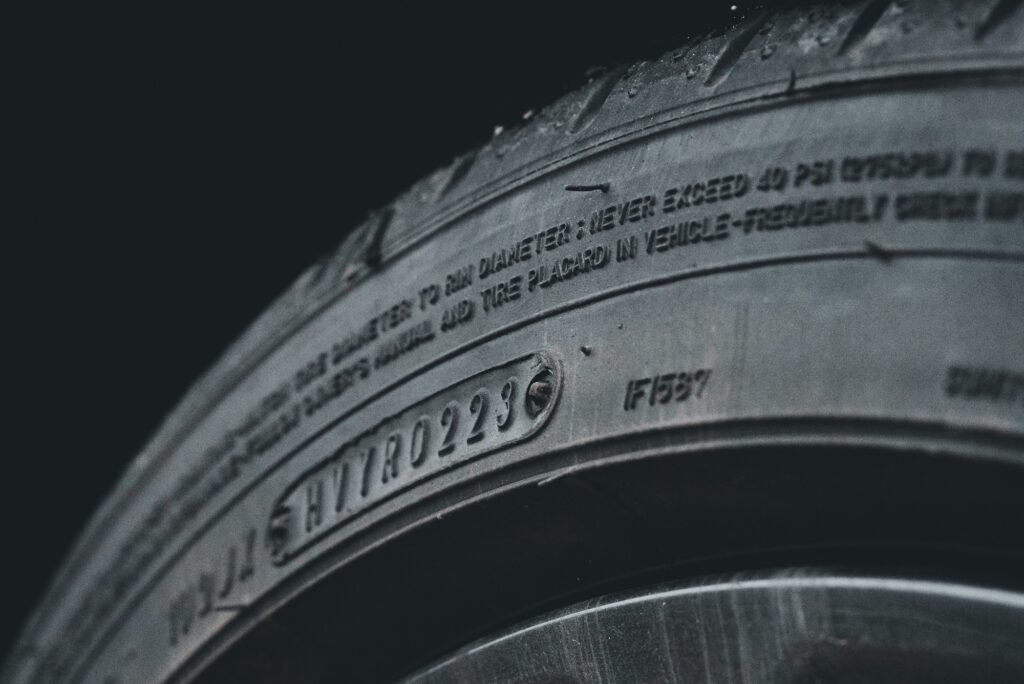
Tyre pressure modules sit in a mechanical housing on the back side of the valve, within the tyre cavity. They experience thermal shock: ambient temperature of -40°C in winter to 125°C when brake heat soaks into the rims during hard driving. A 165°C operating range stresses both sensor and compensation circuit.
Modern TPMS ICs often use hybrid compensation: analogue circuits adjust gain and offset, whilst a digital lookup table in EEPROM corrects higher-order nonlinearity identified during manufacturing calibration.
Industrial condition monitoring
A vibration sensor for predictive maintenance might experience -20°C in winter storage and +80°C near machinery, operating reliably for 20-30 years. This longevity requirement changes compensation strategy.
Rather than optimising for a narrow temperature window, industrial ASICs must ensure compensation remains stable over decades. To demonstrate that compensation accuracy is maintained after accelerated stress, this demands:
- compensation algorithms robust to component ageing (resistor drift, current mirror ageing)
- qualification testing (HTOL at 125°C for 1,000 hours or more)
Here, the ASIC advantage is clear. A pre-built signal conditioner has a commercial product lifecycle of 5-10 years. Your industrial system may demand support for 20-30 years. An ASIC can extend your supply window significantly. When end-of-life becomes unavoidable, a good supplier will proactively work with you, supporting last-time buys and process migration, rather than simply discontinuing the product.
Trade-offs: choosing your compensation path
Every compensation choice involves trade-offs across multiple dimensions.
Accuracy vs. power consumption
Analogue compensation is conceptually simplest and lowest cost, but typically achieves lower accuracy because it can only correct first-order temperature effects. Digital compensation adds design complexity and cost, but delivers the higher accuracy needed when sensor nonlinearity is significant. Hybrid approaches balance complexity and cost against accuracy, capturing most of digital compensation’s accuracy gains without the full overhead.
Optimisation vs. flexibility
An ASIC tuned specifically for one sensor type and one operating envelope is smaller and lower power than a generalised design. However, if your sensor supplier changes or your application expands to a wider temperature range, a tuned ASIC may require redesign. Deciding how much flexibility to embed at the specification phase is critical.

Specifying compensation: getting it right from the start
Temperature compensation is central to sensor reliability, accuracy retention, and field performance. The choice of compensation method, calibration strategy, and temperature sensor integration cascades through your entire ASIC design and affects power, area, accuracy, and long-term supply resilience.
Swindon Silicon Systems has 40+ years of experience designing mixed-signal sensor ICs for automotive, industrial, and aerospace applications. We understand the thermal extremes of TPMS modules, the long-lifecycle demands of industrial condition monitoring, and the qualification rigour required to prove compensation performance over time. We have deep expertise in compensation architecture trade-offs, on-die temperature sensing, calibration strategies, and the design-for-test disciplines that ensure compensation circuits pass manufacturing and perform reliably in the field.
If you are specifying a sensor ASIC, speak to Swindon Silicon Systems about your temperature compensation challenge. We can help you design a solution that meets your accuracy targets, operates reliably across your full operating environment, and remains available throughout your product’s lifecycle.